

Table of Contents
ToggleIntroduction
The nRF54L15 is Nordic Semiconductor’s fourth-generation Bluetooth Low Energy chip. It brings Bluetooth 6.0, Channel Sounding, Thread and Matter support, and a much faster processor than the nRF52 series it succeeds, alongside expanded non-volatile memory and RAM.
Before any firmware is written, every nRF54L15 project faces the same hardware decision: design the chip directly onto your own board (chip-down), or use a ready-made module that already contains the chip, antenna and supporting components.
There is no single right answer. This article sets out what each route involves, where the effort and risk sit, and how to decide which suits your product.
What’s new in the nRF54L15 for designers
Compared with the nRF52 series, the nRF54L15 gives designers more processing headroom, more memory and new radio features, in the same low-power class.
- Processor and memory: an Arm Cortex-M33 at 128 MHz, with 1.5 MB of non-volatile memory and 256 KB of RAM. Enough to run application code, a protocol stack and some on-device processing on one chip.
- Bluetooth 6.0 and Channel Sounding: Channel Sounding measures the distance between two devices far more accurately than signal strength alone. It opens up applications such as digital keys, asset finding and proximity-based access.
- Multiprotocol radio: Bluetooth LE, Bluetooth Mesh, Thread, Matter and IEEE 802.15.4, plus NFC.
- Security: PSA Certified Level 3, which matters for products that must meet the EU Cyber Resilience Act.
- Operating range: a 1.7 to 3.6 V supply and an extended temperature range of -40 to +105 °C.
Nordic’s nRF54L15 product page has the full specification.
What a chip-down design involves
Putting the nRF54L15 directly on your board gives the most control, but the radio design and the certification become your responsibility.
RF matching and the antenna. The chip needs a matching network between its radio pins and the antenna, tuned for your board. The antenna itself, whether a PCB trace, a chip antenna or an external one, must be designed for your enclosure. Plastics, batteries, metal parts and even the user’s hand all detune it. Getting good range in a small product usually takes several board spins and RF test equipment. Our white paper What affects real-world RF performance covers this in more detail.
Clocks and power. A chip-down design needs a 32 MHz crystal, a 32 kHz crystal for the lowest-power sleep modes, and the inductor and capacitors for the DC/DC converter. Each must be chosen, placed and laid out to Nordic’s reference design.
Layout. RF layout rules constrain the board: a controlled-impedance feed, a clean ground plane, and keep-out areas around the antenna. This often drives the layer count and the shape of the whole board.
Certification. Every product that transmits must be approved for each market it is sold in: CE (RED) in Europe, FCC in the US, ISED in Canada, TELEC in Japan, KC in Korea, and others. With a chip-down design, the full radio testing falls on your product. Each new market adds test time and cost. [check: add typical cost or timeline from our experience, if we want to quote one]
Bluetooth qualification. Products using Bluetooth must also be listed with the Bluetooth SIG.
What a module takes off your plate
A module moves the radio design and most of the certification work from your project to the module maker.
Take the ISP2454 as an example. It is an 8 x 8 x 1 mm System-in-Package built around the nRF54L15, with the crystals, DC/DC components, RF matching and antenna all inside. Only power is needed to have a working Bluetooth LE link.
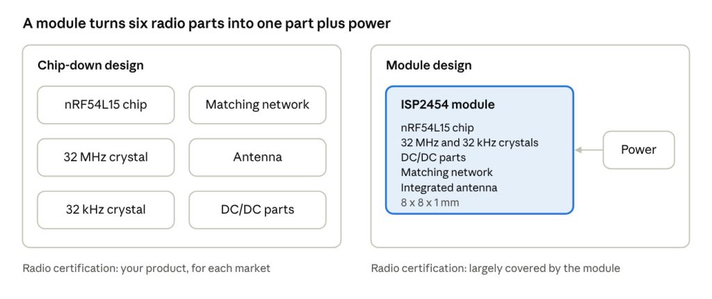
With a module, the six radio parts on the left become one component on your board.
- The antenna is already designed. The integrated antenna is tuned within the package, so you follow a few placement rules rather than designing and tuning an antenna yourself.
- Pre-certified for the main markets. The module carries its own radio approvals. Your product can use these directly, which removes the need the radio testing dedicated radio testing needed for certification. Certification is complete for the US, EU, UK and Japan. Insight SIP can discuss additional certifications.
- Simpler layout. No RF feed or matching network to route, and fewer components to place, so the board can often be smaller and use fewer layers. Most customers will not be able to make a design as small as Insight SIP’s module.
- Faster, lower-risk development. Fewer board spins and less RF test equipment mean a shorter path to first prototypes and to production.
- Simpler production. Fewer parts to source, place and test on the production line. Insight SIP monitors lead times and issues on all components, and informs customers.
- Support on any RF issues. Insight SIP will review customer layouts for any issues. In case of unexpected poor performance, Insight SIP offers support to resolve issues.
At 8 x 8 mm, the ISP2454 is one of the smallest nRF54L15 modules available, which matters most in wearables, sensors and other space-constrained products.
The trade-offs: when chip-down makes sense
A module is not always the right choice. Chip-down can be the better route when:
- Volumes are very high. At hundreds of thousands of units a year or more, the lower bill of materials of a chip-down design can outweigh its extra engineering and certification costs. However, a simple BOM cost comparison is insufficient; the cost of any delayed time to market, additional customer build cost, supply chain management, maintaining certifications (they get revised) and additional yield loss (Insight SIP parts are all fully tested.
- You have an experienced and available RF team and the test equipment to go with it, so the design risk is lower.
- The product needs an unusual antenna, for example an antenna built into a metal housing or a large external antenna for very long range.
- The layout is unusual, such as a flexible or very thin board where a module’s footprint does not fit.
For the volume trade off, it isn’t easy to give a precise figure, as a lot depends on the nature of the product being designed and the organisation that is doing it. However, a good engineering principle is “don’t re-invent the wheel”. In general, for anything not in the hundreds of thousands the cost savings are illusory, particularly if time to market matters.
Chip-down or module: a quick guide
The more of your answers fall in the module column, the stronger the case for a module.
Question | Points to a module | Points to chip-down |
|---|---|---|
Annual volume | Low to medium/high | Very high |
Time to market | Tight | Flexible |
RF expertise in-house | Limited | Experienced RF team and test equipment |
Target markets | Several regions (EU, US, Japan, Korea and more) | One or two regions |
Product size | Small, space-constrained | Room for an antenna and keep-out area |
Antenna needs | Standard range, integrated antenna is fine | Special antenna or very long range |
Design risk tolerance | Low: first time right matters | Can absorb extra board spins |
Migrating from nRF52-based designs
If your current product uses an Insight SiP nRF52 module, moving to the nRF54L15 can be a drop-in hardware upgrade.
The ISP2454 is pin-to-pin compatible with the ISP1507 (nRF52832), ISP1807 (nRF52840) and ISP1907 (nRF52833) series. The new module fits the existing footprint, so the board does not need to be redesigned to gain Bluetooth 6.0, Channel Sounding, the faster processor and larger memory. Note that although it in general offers improved performance the ISP2454 (nRF54L15) does not support all the features of the top end nRF52 series modules; the ISP2554 may be required for some features (e.g. USB peripheral)
For a chip-down nRF52 design, the move to the nRF54L15 means a new layout, new RF tuning and new certifications. That makes a migration a natural point to reconsider the module route.
Firmware still needs porting, since the nRF54 series uses Nordic’s nRF Connect SDK. For the nRF54 there are two options: Zephyr real-time OS or the “bare-metal” SDK which is similar to the old “Soft Device” used in the nRF52.
Getting started with the ISP2454
You can evaluate the nRF54L15 in module form straight away, using the same tools you would use for a chip-down prototype.
- ISP2454-LX-EB evaluation board: an interface board with an integrated J-Link OB programmer and debugger, plus a test board. Everything needed for hardware and software development.
- ISP2454-LX-TB test board: the module on a small PCB with test points for every I/O and an integrated NFC antenna. It works with Nordic’s nRF54 development kits and external J-Link programmers.
- Design files: datasheets, Altium and Eagle footprints, a 3D STEP model, and test board schematics and Gerber files, all on the ISP2454 page.
Three variants cover different needs: the ISP2454-LL (basic, 32 MHz crystal), the ISP2454-LX (standard, with the 32 kHz crystal for lowest-power sleep) and the ISP2454-LP (premium, with 4 MB of extra flash).
Next steps: buy the ISP2454-LX and development tools online, or contact us to discuss your design or a custom module.